Let’s discuss the question: how to calculate rise time and fall time. We summarize all relevant answers in section Q&A of website Achievetampabay.org in category: Blog Finance. See more related questions in the comments below.

How do you calculate rise time?
y(t)=L−1{Y(s)}=L−1{H(s)1s}=L−1{as(s+a)}=L−1{1s−1s+a}=1(t)−e−at. We define rise time as the time it takes to get from 10% to 90% of steady-state value (of a step response). Rise time is denoted tr. Figure 1 shows the rise time of step response of a first order transfer function.
How are the rise time and fall time are measured?
Rise time is typically measured from 10% to 90% of the value. Conversely, fall time is the measurement of the time it takes for the pulse to move from the highest value to the lowest value.
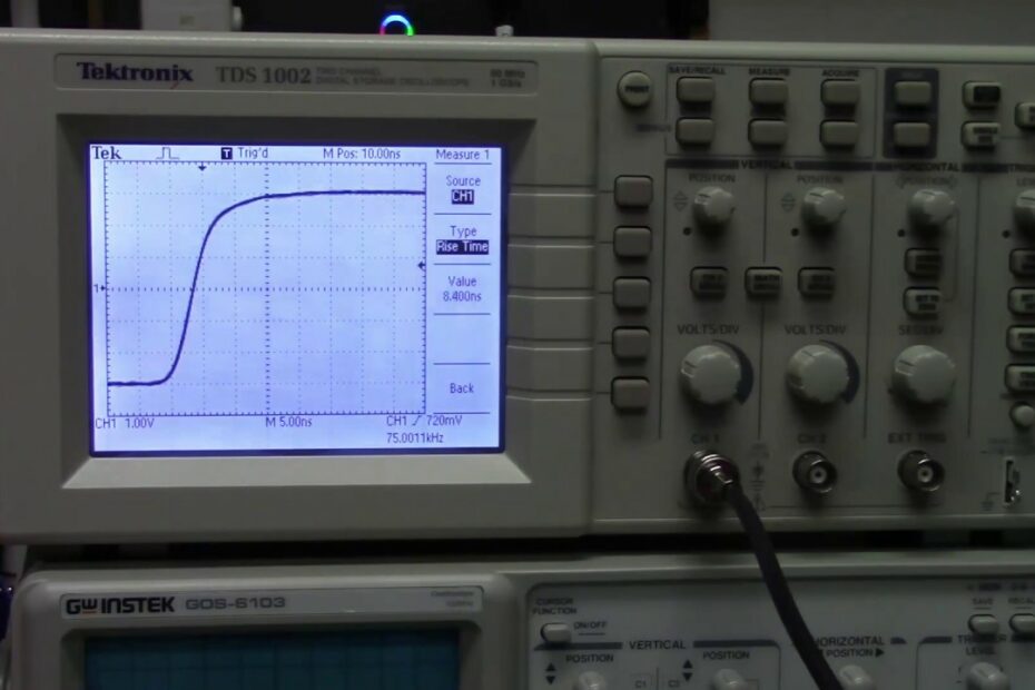
3. Measuring Rise Time and Fall Time with an Oscilloscope
Images related to the topic3. Measuring Rise Time and Fall Time with an Oscilloscope
Why is rise time greater than fall time?
The rise time at the output depends primarily on how fast the P channel device can turn on, and the fall time is determined primarily by how fast the N channel device can turn on.
How do you calculate rise time and fall time of a Mosfet?
…
CSD19503KCS: MOSFET rise time and fall time check.
| Vgs Rise /Fall Time | Typ(nS) | Max(nS) |
|---|---|---|
| t1R | 10.2 | 18 |
| t2R | 12.83 | 22.57 |
| t3R | 12.98 | 22.5 |
| t4R | 14.8 | 26 |
What is signal rise time?
Rise time. Rise time is the time taken for a signal to cross a specified lower voltage threshold followed by a specified upper voltage threshold. This is an important parameter in both digital and analog systems.
How does oscilloscope measure rise time?
- Rise time (in seconds) = 0.35/bandwidth (in Hz), or.
- Bandwidth (Hz) = 0.35/rise time(s)
How does Matlab calculate rise time?
Description. r = risetime( x ) returns a vector, r , containing the time each transition of the input bilevel waveform, x , takes to cross from the 10% to 90% reference levels. To determine the transitions, risetime estimates the state levels of the input waveform by a histogram method.
How do you find the rise time of a first order system?
Time Constant of a First Order Control System
The time constant can be defined as the time it takes for the step response to rise up to 63% or 0.63 of its final value. We refer to this as t = 1/a.
Why do we need equal rise and fall time?
On that note, in a digital system the clock rate is constant. If you had a slower rise or fall time then the clock rate would have to be designed for the slower signals. By having matching rising and falling times your clock matches the speed of both.
Rise Time and Fall Time|Basic Circuit Concepts|VLSI|Krishnaveni D
Images related to the topicRise Time and Fall Time|Basic Circuit Concepts|VLSI|Krishnaveni D

What is rise time and peak time?
If the signal is over damped, then rise time is counted as the time required by the response to rise from 10% to 90% of its final value. Peak time (tp) is simply the time required by response to reach its first peak i.e. the peak of first cycle of oscillation, or first overshoot.
How do you measure fall time on an oscilloscope?
Annotation labels identify the threshold levels on each end of the waveform’s negative (falling) edge. The fall time will not be measured until the falling edge completes the transition through all three levels. The fall time equals the lower threshold crossing time minus the upper threshold crossing time.
What is rise time Mcq?
Time taken for the response to raise from zero to 100 % for very first time is called rise time. For under damped system it is 0 – 100 %, for over damped system it is 10 – 90 % and for critically damped system it is 5 – 95 %.
What is rise time in VLSI?
Rise time (tr) is the time, during transition, when output switches from 10% to 90% of the maximum value. Fall time (tf) is the time, during transition, when output switches from 90% to 10% of the maximum value. Many designs could also prefer 30% to 70% for rise time and 70% to 30% for fall time.
What is rise time in MOSFET?
The time from when the gate-source voltage rises over 10% of VGS until the drain-source. voltage reaches 90% of VDS. (2) tr: Rise time. The time taken for the drain-source voltage to fall from 90% to 10% of VDS.
How is RG calculated in MOSFET?
T= RgC time constant, Should be less than(10 times) to the rise time of MOSFET given in datasheet . That is how we can calculate Rg value .
How is MOSFET gate current calculated?
Since the gate current is constant, the time axis can be expressed in terms of gate charge Qg by multiplying time by constant gate current IG. (The gate charge is calculated as Qg=IG×t.) The gate of a MOSFET starts accumulating electric charge when a voltage is applied to it.
30 May 2020, VLSI, Rise time and fall time estimation of a CMOS inverter
Images related to the topic30 May 2020, VLSI, Rise time and fall time estimation of a CMOS inverter

What is fall time of a signal?
In electronics, fall time (pulse decay time) is the time taken for the amplitude of a pulse to decrease (fall) from a specified value (usually 90% of the peak value exclusive of overshoot or undershoot) to another specified value (usually 10% of the maximum value exclusive of overshoot or undershoot).
What does 100mhz oscilloscope mean?
Specifically, it determines the maximum frequency that the instrument can accurately measure. Bandwidth is also a key determining factor in price. Determine what you need – use the ‘five times rule’ For example, a 100 MHz oscilloscope is usually guaranteed to have less than 30% attenuation at 100 MHz.
Related searches
- rise time
- Fall time
- time rise formula
- A typical pulse fall time is measured as
- rc time constant calculator
- Rise time
- how to measure rise and fall time in oscilloscope
- how to calculate rise time and fall time in cadence
- formula for rise time
- how to find rise time from transfer function
- bandwidth and rise time
- what is rise time and fall time
- Trise rising time
- Bandwidth and rise time
- settling time
- How to find rise time from transfer function
- rise time and fall time in vlsi
- trise rising time
- fall time
- how to calculate rise time and fall time of mosfet
- a typical pulse fall time is measured as
Information related to the topic how to calculate rise time and fall time
Here are the search results of the thread how to calculate rise time and fall time from Bing. You can read more if you want.
You have just come across an article on the topic how to calculate rise time and fall time. If you found this article useful, please share it. Thank you very much.